


DSC – Differental Solar Controller
The DSC is an Arduino based differential solar controller for a domestic solar hot water system. It features:
- Low-cost. Built it yourself for less than $100 in parts.
- LED display indicates power, pump, over-temperature, and low-water.
- Supports monitoring/logging via serial port.
- Inlet and Outlet sensors to determine heat-exchanger efficiency.
- Easily customizable firmware.
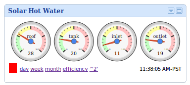
When connected to the Internet, the DSC allows temperatures and pump status to be monitored and graphed using a Google Gadget.
The DSC was created to replace a differential solar controller that came with a solar hot water system originally purchased and installed in Ontario in 1982. In 2009, the system was moved to British Columbia, upgraded, and re-installed, with PEX instead of copper pipe, a new handmade heat exchanger, and a modern differential controller.
How it Works
In simplest terms, this project is a fancy temperature-controlled relay, and could easily be adapted to monitor the temperature of other things, or control appliances other than circulating pumps.
Four temperature sensors monitor the holding tank, solar panel, and inlet and outlet of the heat exchanger. An Arduino, using a custom shield, reads temperatures every few seconds. If the roof is hotter than the holding tank, a relay turns on the circulating pump. The pump turns off when the tank is at maximum temperature or the roof is cooler than the tank. If the water level in the holding tank gets too low, an alarm will sound.
In addition to controlling the pump, the Arduino also sends temperature readings to a host computer via serial port, where the readings are parsed, stored, graphed, and published online.
I no longer live in the house in which this system is installed, so I no longer have access to live data generated by the system.
Technology
The DSC uses an Arduino Uno, a custom Arduino shield, and Dallas 1-Wire temperature sensors connected via Cat5 cable. Linux Cron jobs record temperatures, generate graphs, and update the Google Gadget.
Limitations
There are two limitations to this controller that must be known before spending the time and effort to build and install a DSC controller.
First is the maximum operating temperature of the 1-wire temperature sensors, which is 125C. Temperatures in excess of 125C are not uncommon inside the solar panel and can melt, damage, or short-circuit the sensor. (On several occasions the shrink-wrap and wire insulation has melted into a giant blob causing the roof sensor to short-out the entire 1-wire bus).
Second is the monitoring scripts and gadget, which were never intended to be public. They contain hard-coded values and are generally not very user-friendly. See the “To Do” section at the bottom of the page for details.
How to Build
It is assumed that you already have (or are planning to install) your own solar hot water system and that you have basic knowledge of household electrical and pump wiring.
Source code and Eagle project files (schematic and PCB layout) are available on GitHub. Please use the Issue Tracker for support.
Materials
 First, some basic requirements:
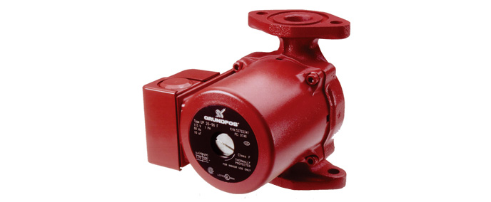
- a 5A (or less) 120V circulating pump, like a Grundfos or a Taco
- a holding or heat-exchanger tank
- a solar hot-water panel, ideally with a thermometer well
If you don’t have these things, you probably don’t need a differential solar controller, unless you’re adapting the project for some other use. To build the hardware, you’ll need:
- an Arduino (Uno or similar – compatible with standard Arduino ‘shields’)
- optional (for monitoring): an Internet-connected laptop, RaspberryPi, or PC. Current scripts will only run on Linux, but custom software could be written for Windows.
- a length of Cat5 cable long enough to reach the controller, inlet, tank, outlet, and roof panel with an 8P8C connector on one end.
- a proto-shield, breadboard, or a “dsc-1” PCB.
Update: The dsc-1 PCB once was available directly for purchase from BatchPCB, the now defunct small-run board house. If you’d like a professionally fabricated PCB, you can simply upload the Eagle Board File to OshPark. The Github repository contains everything you need to prepare designs for other board houses as well, including Gerber files.
To build the circuit board, you’ll need basic soldering tools and the following parts. I’ve supplied Digikey part numbers for populating the dsc-1. If you use a different supplier, the Digikey website will give you manufacturer 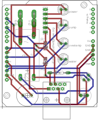 part numbers as well as datasheets.
- 2 x 1287K-ND, Quickfit Terminals
- 1 x 1N4148, Diode
- 1 x Z139-ND, Relay
- 1 x IRLB8748PBF, Mosfet
- 1 x 311-10.0KFRCT-ND, 10K Resistor
- 1 x 311-4.70KFRCT-ND, 4.7K Resistor
- 1 x 380-1046-ND, 8P8C Jack
- 1 x 445-2525-1-ND, Piezzo Buzzer
- 1 x 490-3811-ND, 0.1uF Capacitor
- 2 x 67-1120-ND, Red LED
- 2 x 67-1119-ND, Green LED
- 1 x 770-61-R150P-ND, Resistor Network
- 1 x S1012E-30-ND, 30-position header pins (break into 4 smaller pieces)
- 4 x DS18S20+CT-ND, 1-Wire Temperature Sensors
The relay specified here can switch 120V pumps up to 5A. If your pump draws more than this, you’ll need to use a different relay. Instead of quickfit terminals you can use simple wire leads. If you are using a proto-board instead of the dsc-1 PCB, you don’t need the header pins and may also want to substitute the SMD resistors for through-hole parts. Also, if you are planning on installing the controller in an enclosure, some LED lenses (L30002-ND) might be handy.
Assemble
Controller
Build the circuit according to the following schematic. You can also get the Eagle project files for the schematic and board from GitHub if you want to make changes and spin a new PCB.
Wire the pump through P1 and P2. Mate the shield with the Arduino, and provide the Arduino with the appropriate DC voltage.
Sensors
At minimum, you’ll need a 1-wire temperature sensor inside the solar panel and another one affixed to (or immersed in) the holding tank. For a full-monitoring solution, add 2 more sensors to monitor the input and output of the heat exchanger.
Use a single strand of Cat5 cable to form a bus for the 1-wire temperature sensors. The Cat5 cable is run from the controller, past the heat exchanger (for input, output, and tank sensors), then up onto the roof and into the temperature sensor well inside the solar collector. Connect the Cat5 cable to the controller using an 8P8C connector and TIA/EIA-568-B wiring.
Solder a 6″ wire lead to each leg of the four 1-wire sensors. Use higher-temperature wire for the roof sensor (125 C +). Wrap leg #2 in 1/8″ heat-shrink, then wrap the entire device (all three legs and part of the semiconductor) in 1/4″ heat-shrink. Affix one sensor to the input to the heat exchanger, one to the surface of the holding tank, one to the output of the heat exchanger, and one in the thermometer well of the solar array. If you don’t have a well, or want to immerse the sensors, you can insert them into capped copper pipe or metal knitting needles. I find sticking them to the surface of the pipe or tank with electrical tape works well enough.
If you want to test your sensors before installing them, you can use the "scanbus" sketch. See the Firmware section below.
Connect the temperature sensors to the Cat5 bus using telephone 2-Wire Tap Splice (blue) connectors. Be sure to crimp them tightly so that all the wires make solid contact. Use the following wiring scheme:
- Blue = DQ (pin 2)
- Blue/White = GND (pin 1)
- Orange = +5V (pin 3).
(If you happen to be using TIA-5680A wiring, connect pin3 to Green instead of Orange.)
The controller also supports a low-water sensor, such as a float-switch. The low-water alarm is active-low and is connected to Pin 1 (orange/white) of the Cat5 bus.
Firmware
Get the firmware source from GitHub:
git clone https://github.com/angryelectron/dsc.git
The DSC sketch depends on the DallasTemperature and OneWire libraries. You can install them separately, or change the Sketchbook Location in the Arduino IDE (File -> Preferences) to point to the dsc-sketchbook directory to include the libraries automatically.
Upload the “scanbus” sketch to the Arduino, then open the IDE’s Serial Monitor. If the hardware is working and the sensors are connected, you will see 4 16-bit addresses, one corresponding to each temperature sensor. The temperatures should help you deduce which sensors are which.
/*
 * Modify the settings below to match your hardware.  Temperatures in degrees Celsuis.
 */

#define HIGHTEMP_LIMIT  90      /* shut off when this temperature is reached */
#define OVERTEMP_LIMIT  85      /* restart after an over-temperature condition at this temperature */
#define DELTA_ON        10      /* collectors must be this much warmer than the tank before turning on */
#define DELTA_OFF       2       /* collectors must be this much warmer than the tank before turning off */

/* Define the addresses of the temperature sensors below.  The 'Multiple' example sketch in the DallasTemperature
   library can be used to discover devices and addresses on the 1-Wire bus.
 */
DeviceAddress roofSensor = {0x10, 0x1f, 0x4d, 0x83, 0x02, 0x08, 0x00, 0xE9};
DeviceAddress tankSensor = {0x10, 0x25, 0x39, 0x57, 0x00, 0x08, 0x00, 0xf9};
DeviceAddress inletSensor = {0x10, 0xb2, 0x58, 0x83, 0x02, 0x08, 0x00, 0x51};
DeviceAddress outletSensor = {0x10, 0x76, 0xb4, 0xd2, 0x01, 0x08, 0x00, 0x5a};
The next step is to open and configure the “dsc” sketch. In “dsc.h”, you can set the on/off/delta limits for the controller in degrees Celsius, as well as the addresses of the temperature sensors displayed by the “scanbus” sketch. Compile and upload the sketch once all the values have been set. If everything is working, you should see 4 bytes appear in the Serial Monitor every 1-2 seconds. These bytes correspond to the roof, tank, inlet, and outlet temperature in Hex, and is what the monitoring software will use to record and display data.
Monitor and Program
The DSC controller sends temperature readings via serial port every 1-2 seconds. You can write scripts to capture, record, and display this data. Here’s all you need to know:
- By default, the serial port uses 9600 / N / 8 / 1.
- Each reading is displayed on a single line containing 4 bytes. Each hex byte corresponds to the temperature (in Celsius) of the roof, tank, inlet, and outlet sensors.
- Negative roof temperatures are displayed using Two’s compliment.
The “scripts” directory included with the project source files contains an Bash script that I use to read and record data using RRDTool. These scripts are probably quite specific to my setup and will require some adaptation, but are included for inspiration. Called from Cron jobs, the dsc-monitor script reads data from the serial port and adds it to the rrd database. It also outputs an XML file which can be read by the Google Gadget. The other scripts generate graphs for various periods and parameters.
In the “gadget” directory is a Google Gadget which reads an XML file containing the latest temperature data and provides links to various graphs. It doesn’t handle two’s compliment, which is why -1C displays as 254C. Again, it will need to be adjusted for your particular setup.
To Do
Here are some things that could use some work and/or ideas for improving the project in the future:
- Package / enclosure. The “shield” style PCB makes it difficult to build an enclosure with neat, panel-mounted LEDs.
- Monitoring software. A platform-independent and user-customizable monitoring tool is required.
- Cloud. The monitoring tool could upload data to a web application which would process and display the data from multiple systems without requiring a Linux server at home.
- Implement the low-water sensor.