The Beta 240 is a (long discontinued) hot-tub spa-pak made by Aqua Spa Pak. There is limited information about this unit available online, and the intent is to provide as much information as possible as I troubleshoot and repair a unit that came with a house I bought.
For good background information about spa components, testing, and troubleshooting, I recommend the Spa Repair Handbook from Central Spa Supply. I have also received helpful information and advice from Poolside Spa Sales & Service.
Safety Precautions
The standard precautions for working with electricity apply, especially as this is a 240V unit and is usually located near water. Don’t even consider opening up your spa-pak if you don’t know what you are doing around high-voltage electricity.
Check water temperature with a thermometer, especially when troubleshooting issues with the thermostat and/or high-limit switch and use extreme caution around water hotter than 104F.
General Description
All components in this spa pak use 240VAC supplied through the “panel” side of a GFCI breaker. The load-neutral leaving the GFCI breaker is not used as none of the components require 120V, but the line-neutral (white pigtail) must be connected for proper GFCI protection.
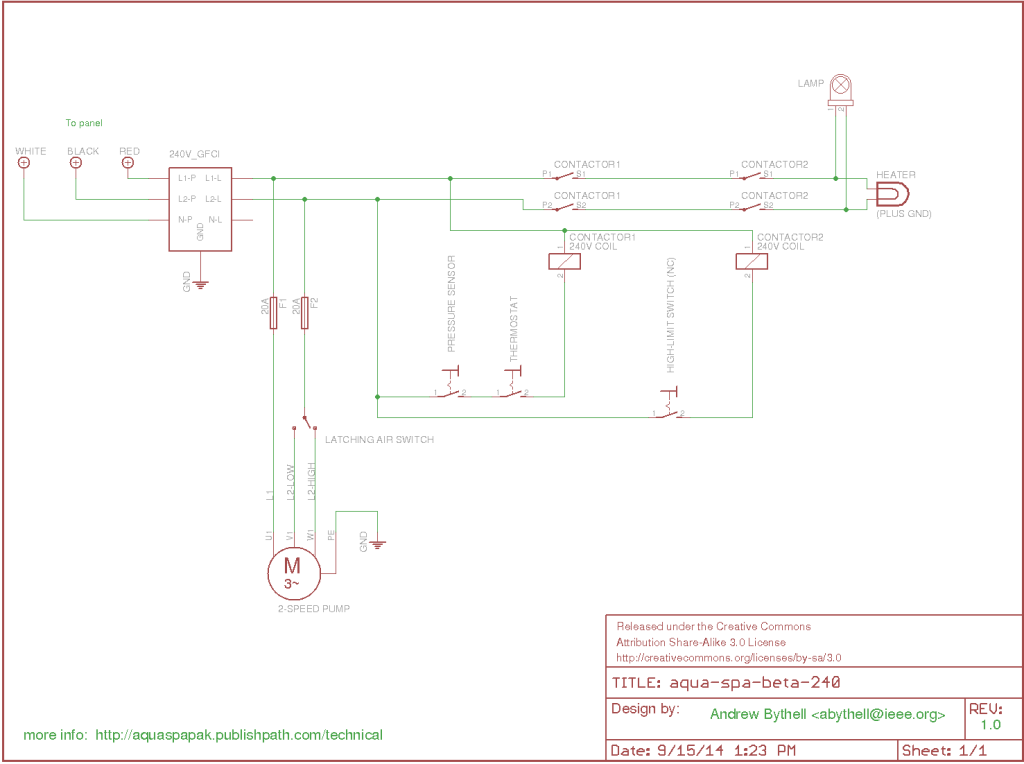
The two-speed pump runs whenever the pak has power. The motor is protected by two 20A fuses on L1 and L2. A latching air-operated switch connects L2 to either the low-speed or high-speed windings of the pump’s motor. Pumping the plunger (mounted tub-side) forces air into the switch and toggles between speeds.
The heating element will turn on, and the lamp will illuminate only if:
- the high-limit switch is below the max temperature (normally closed) – somewhere around 120F
- the pressure sensor detects adequate water pressure around the heating element (normally open)
- the thermostat is calling for heat (depends on the dial setting)
The pressure sensor is in series with the thermostat, requiring both be Closed/ON before the main contactor will close. The high-limit switch controls the second contactor, which is normally closed unless an over-temperature condition is encountered.
Schematics and Drawings
The only information I could find online is the Aqua Spa Diagram, which in my opinion is not an accurate diagram nor one that is easily interpreted, so I drew a proper schematic.

Beta 240 Schematic – Click for PDF. The symbol used for the motor indicates 3-phase, but in fact the motor is single phase 240V with high and low-speed windings.
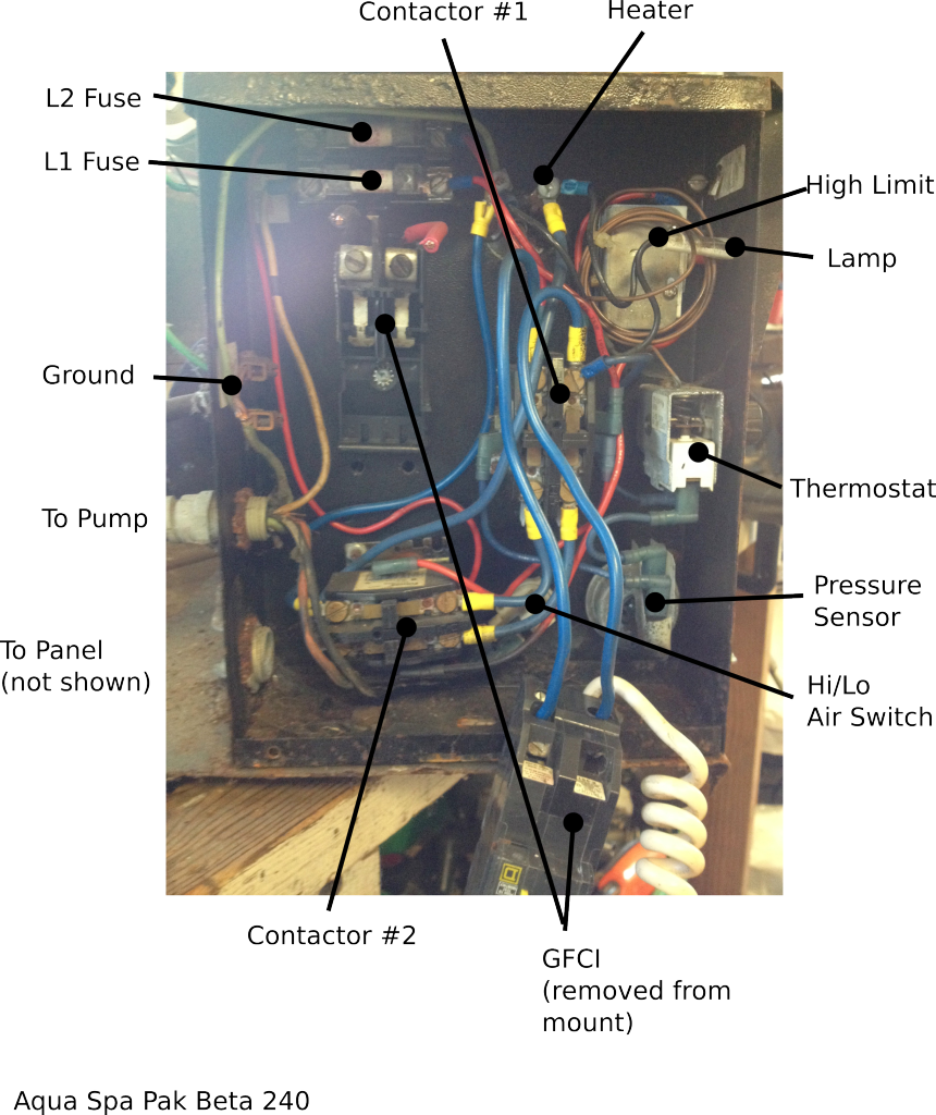
Here is a photo which has been annotated to show the locations of all the components:
Test Measurements
- Heater: 11 ohms
- Contactor Coils: 900 ohms
- High-Limit Switch: normally closed, opens when bulb heated with blow torch.
- Pressure Sensor: normally open, closes when pressure is applied (use a bicycle pump)
- Thermostat: open when rotated fully counter-clockwise. Should close when rotated clockwise.
- Contactors: normally open. #2 should close immediately when power is applied, #1 should close when pressure is present and thermostat calls for heat.
Component Details
Contactors
- Switching Voltage: 240V AC
- Switching Current: 20A (min)
- Coil Voltage: 240V AC (min)
- DPST
- Normally-open
- Chassis-mount
GFCI Breaker
- 50A breaker
- 240V
- 2-pole
- 5mA ‘trip’ current
Quick Fixes
- Use sandpaper to clean up the contacts on buzzing contactors.
- Use gas line to replace old/cracked pressure tubing for the Hi/Lo switch or the pressure switch
Go Digital
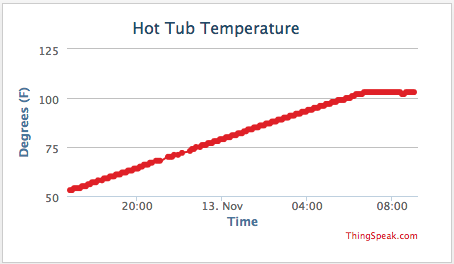
After a while messing around with these “analog” components, I decide to replace one of the contactors, the theromstat, and high-limit switch with a temperature-controlled relay. I built one myself using an Arduino and a 1-Wire temperature sensor (details here). It has the added feature of transmitting temperature readings over a wireless network, which I send through an XBMQ gateway to Thingspeak for logging and graphing.


